













Inert Gas Pressure Relief Venting: Why a Sealed Room Still Needs Pressure Management
An inert gas suppression room has to do two things that sound contradictory. It has to hold agent concentration for the required period, which means controlling leakage. And it has to release pressure during discharge, which means having a deliberate opening. Pressure relief venting is how a room does both: a vent that stays shut during normal operation and during the hold time, and opens for the few seconds when the enclosure would otherwise be over-pressurized.
Sealing the room tighter does not solve the second problem. It makes it worse. That matters most on inert gas systems, because the entire agent quantity arrives as gas, and the volume introduced is large enough that venting is rarely optional.
Explore further
Key takeaways
- Hold time and peak discharge pressure are separate problems. A tighter room helps one and hurts the other.
- Inert gas systems generally need far more free vent area than halocarbon systems protecting the same volume, because there is no vaporization cooling to offset the added gas.
- A relief vent is a listed assembly, not a gap, a propped door or a lifting ceiling tile.
- A passing door fan test says nothing about whether the structure can withstand peak discharge pressure.
- The allowable enclosure pressure belongs to the client or structural designer. Without that figure, the sizing calculation has no answer.
Inert gas systems are clean agent systems
Worth settling the terminology before anything else, because it causes confusion in specifications and in vendor conversations.
Inert gas agents are clean agents. IG-01 (argon), IG-100 (nitrogen), IG-55 and IG-541 sit inside NFPA 2001 and ISO 14520 alongside halocarbon agents such as FK-5-1-12, HFC-227ea and HFC-125. "Clean agent" is the category. "Inert gas" and "halocarbon" are the two families inside it, and they behave differently enough that venting has to be designed for the family actually installed.
Carbon dioxide systems are a separate case, governed by their own standard rather than NFPA 2001, and are not covered here.
Why inert gas rooms must retain agent yet manage pressure
Two different requirements get confused because both involve how leaky the room is.
Enclosure integrity and hold time is about the minutes after discharge. The agent has to stay at design concentration long enough for the fire to be controlled and, where applicable, for responders to arrive. A ten-minute hold time is common. Leakage works against you here.
Peak discharge pressure is about the seconds during discharge. Agent entering the enclosure displaces or adds to the air already there, and the enclosure has to shed that pressure somewhere. Leakage works for you here, but only if there is enough of it and it is in the right place.
A room can pass a hold-time assessment and still be structurally at risk during discharge. The two are assessed separately, and a tight room can fail the second test precisely because it passed the first.
People also search
What happens during inert gas discharge
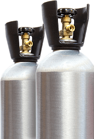
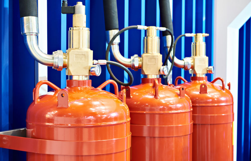
Inert gases are stored as compressed gas and discharged as gas. There is no liquid phase to vaporize, so there is no cooling effect to offset what is being added to the enclosure. The result is a positive pressure excursion only, most of it arriving very early in the discharge. The vent has to be open and large enough at that moment, not a second later.
Halocarbon agents behave differently, and the contrast explains why the two families need different vent areas. Those agents are stored as liquids and vaporize on discharge. UK Fire Industry Association guidance notes that vaporization can cool the enclosure air enough to produce an initial negative excursion before the positive one, which is why bidirectional vents exist for halocarbon rooms. The size of that swing depends partly on humidity, which is why the FIA calculation method assumes a relative humidity value when the actual figure is unknown.
That behaviour follows directly from how inert gas systems store and deliver agent .
Agent families and pressure behaviour at a glance
The source data for this table sits across a UK industry guidance document and standards commentary that are rarely read end to end. It is consolidated here as a reference, not as a substitute for a project-specific calculation.
| Inert gas agents | Halocarbon agents | |
|---|---|---|
| Examples | IG-01, IG-100, IG-55, IG-541 | FK-5-1-12, HFC-227ea, HFC-125, HFC-23* |
| Stored as | Compressed gas | Liquefied gas |
| Pressure excursion | Positive only | Positive, and for most agents an initial negative excursion as well |
| Vent type usually required | One-way (positive relief) | Often bidirectional |
| Relative vent area | Substantially larger | Smaller |
| Why | Full agent quantity added as gas, no vaporization cooling | Vaporization cools enclosure air, partly offsetting the added volume |
| Humidity sensitivity | Not a significant sizing input | Significant; assumed value used when unknown |
| Sizing inputs | Mass flow rate, specific vapour volume, design concentration, temperature, flooding factor, allowable enclosure pressure | Agent, enclosure volume, discharge time, design concentration, relative humidity, allowable enclosure pressure |
| Discharge valve effect | Regulated valves extend discharge and generally reduce required vent area | Not applicable in the same way |
* HFC-23 is a halocarbon agent that produces positive excursions only, which is why agent-specific data always beats a family-level assumption.
Published multipliers comparing inert to halocarbon vent area circulate in the trade. We have not found a credible general figure, and the honest answer is that the ratio falls out of the calculation for a specific room and system rather than out of a rule of thumb.
How pressure relief venting works
An engineered vent is a listed assembly, not a hole.
- It stays closed below a set differential, so it does not shorten hold time or leak conditioned air in normal operation. One manufacturer's inert gas vent, for example, is specified to remain closed below 70 Pa and open fully at 100 Pa. That is a product-specific figure, not a general rule.
- It opens quickly at the design differential, usually gravity-weighted or spring-balanced, and reseats afterwards.
- It is directional. One-way vents relieve positive pressure only, which suits inert gas systems. A one-way vent fitted backwards relieves nothing.
- It discharges somewhere safe. The receiving space has to accept the volume without endangering occupants, pressurizing a stair, or pushing agent into an adjacent protected area.
- It sits where the pressure is , normally high in the enclosure.
None of this is the same as an undocumented gap, a door propped open, or a ceiling tile that lifts. Natural leakage can only be counted toward required vent area where room integrity testing supports the figure.
Enclosure integrity testing is not a pressure relief design
The door fan test is often treated as the single proof that a room is fine. It is not.
A door fan test measures leakage area and uses it to predict hold time. Revised test procedures take a second measurement with the vents open, at a higher pressure, to inform the peak-pressure assessment. Even then, what the test does not establish is substantial:
- Whether the walls, ceiling and floor can withstand the calculated peak pressure
- Whether the vent opens at the right differential, in the right direction, with the right free area
- Whether there is leakage above a suspended ceiling that the test cannot see
- Whether the structure has been modified since the last test
Structural resistance is a separate judgement, and it belongs to a structural designer or engineer. A passing room integrity test certificate answers the leakage question, and a room that keeps failing its hold time is still a leakage problem rather than a venting one. Neither result tells you what the structure can take.
What designers need to size a vent
A qualified designer sizing relief for a specific inert gas system will ask for most of the following:
Enclosure
- Internal dimensions and net volume
- Construction type, and the allowable pressure differential the enclosure can withstand
- Known leakage, with test data where it exists
- Shared plenums, ceiling voids, raised floors and any connected volumes
System
- Agent and design concentration
- Actual discharge profile, not a nominal figure
- Design temperature
- Whether the discharge valve is regulated; a longer, controlled discharge generally reduces the vent area required
Boundary
- Ductwork, dampers and their state during discharge
- Where the vent can discharge to, and any external restriction
The one input that is routinely missing is the allowable enclosure pressure. FIA guidance is explicit that this is the client's or structural designer's figure to state, not the suppression supplier's to assume. It depends on the construction in front of you: how the walls are built and fixed, what the ceiling is made of and how it is supported, and what has been changed since the room was built. A figure borrowed from a published table or another project is not an answer, which is why this input has to come from someone who has assessed the actual structure.
Common mistakes in existing rooms
These turn up repeatedly in surveys of installed systems:
- No vent at all , usually in a room that was tightened up after a failed hold-time test.
- Vent fitted the wrong way round , so it relieves into the protected space instead of out of it.
- Vent obstructed by stored material, cable tray, insulation or a later partition.
- Vent discharging into an unsafe or pressurized space , such as an occupied corridor, a stair shaft or another protected enclosure.
- Undocumented penetrations from subsequent fit-out work, changing both leakage and the discharge path.
- No structural review on record , so the allowable pressure was never established.
- Agent quantity changed after a room reconfiguration, without re-running the pressure calculation.
- Free area assumed from the product catalogue , rather than the installed, as-built condition.
Working with HVAC, fire dampers and room boundaries
The enclosure the calculation assumed and the enclosure that exists at the moment of discharge are not always the same room.
Where the sequence of operations shuts down air handling and closes fire or smoke dampers on a confirmed alarm, the leakage area at discharge is smaller than it is in normal operation, sometimes considerably. Where dampers fail to close, or close slowly, the discharge path is different again. Shared ceiling plenums and raised floors can connect the protected enclosure to volumes that were never part of the calculation.
This is a coordination problem across architecture, mechanical and fire suppression design, and it is best resolved on paper before it is resolved by a discharge. The damper timing, the vent sizing and the hold-time assumption all have to describe the same room.
Inspection and retrofit checklist
For an existing inert gas enclosure:
- As-built drawings located, and compared against the room as it stands today
- Agent, quantity and discharge profile confirmed against the current design
- Discharge valve type confirmed, regulated or unregulated
- Allowable enclosure pressure stated on record, by whom and on what basis
- Peak pressure calculation on file for the current configuration
- Vent present, correctly oriented, unobstructed and accessible
- Vent free area and opening pressure match the calculation, as installed
- Discharge path terminates in a space that can safely accept the flow
- Rated construction and penetrations reviewed since the last fit-out
- Room integrity test current, with hold-time result on file
- HVAC and damper behaviour on alarm documented and tested
- Change control in place for future alterations
Vent sizing is a design calculation carried out by a qualified designer against the governing standard and the manufacturer's listed data. It is not a field estimate, and a checklist does not replace it.
Frequently asked questions
Is an inert gas system a clean agent system?
Yes. IG-01, IG-100, IG-55 and IG-541 are clean agents under NFPA 2001 and ISO 14520, in the same standard as halocarbon agents. The two families behave differently on discharge, which is why venting has to be designed for the one installed.
If my room passed its integrity test, do I still need a pressure relief vent?
Very likely. The integrity test addresses leakage and hold time. Whether the enclosure can withstand peak discharge pressure is a separate assessment, and a tighter room is more exposed, not less.
Why do inert gas systems need more venting than halocarbon systems?
Because the full agent quantity arrives as gas with no vaporization cooling to offset it, and the pressure rise is fast. How much more comes out of the calculation for that room and that system.
Can I just leave a door or damper open during discharge?
No. An uncontrolled opening is not an engineered vent. It is unpredictable in size and timing, it compromises hold time, and it may direct agent somewhere unsafe.
Who decides the allowable pressure for the room?
The client or the structural designer, based on the construction actually in place. The suppression designer needs that figure as an input and should not be inventing it.
Does a regulated discharge valve change the vent size?
It can. A regulated valve extends the discharge, which generally reduces the required vent area. The valve type is a sizing input, so it belongs in the calculation rather than being decided afterwards.
Does a bigger vent hurt my hold time?
Not if it is a listed vent that stays closed below its opening differential. A permanently open gap of the same free area would hurt hold time.
How often should vents be checked?
Include them in routine inspection of the suppression system, and re-examine them after any change to the room, the agent quantity or the mechanical systems.
We changed the room layout. Does anything need redoing?
Treat it as a design change. Volume, leakage, penetrations and sometimes agent quantity all shift, which affects both hold time and peak pressure.
Where to go next
If you are responsible for an inert gas suppression system and cannot point to a peak pressure calculation and a stated enclosure pressure limit for the room as it exists now, that is the gap worth closing first. Both are documents, not site work, and both are faster to produce before a modification than after one.
A note on jurisdiction: NFPA 2001 and ISO 14520 are model standards. In Canada they carry legal weight where an adopted provincial code references them, where a project specification calls them up, or where the authority having jurisdiction or the insurer requires them. Confirm which document and which edition govern your site before treating any clause as mandatory.
Need help evaluating fire protection for your facility? Contact Control Fire Systems Ltd. to review special hazard risks, suppression and detection design, system integration, testing, and maintenance requirements.